Views and graphics
This chapter describes the views of the model, how each one is drawn, and how to change what a view shows and how: visual styles, scale and detail level, the view range of a plan, crop regions, hiding and isolating, Visibility/Graphics, filters and view templates. Line weights, line patterns and object styles are described in the same terms by the program's dialogs Manage ▸ Settings.
3D views
View ▸ Create ▸ 3D View ▸ Default 3D View opens the default 3D view, {3D}, framing the whole model; opened again, it shows the model as it was left. Drag to orbit (or Shift and the middle button), drag with the middle button to pan, and turn the wheel to zoom at the cursor; see The interface.
To keep a framing, View ▸ Create ▸ 3D View ▸ Save View: type a name and press Enter. The new view is listed under 3D Views in the Project Browser and opens at once; it keeps the framing it is left with. Renaming {3D} in the Project Browser (right-click ▸ Rename…) does the same: {3D} becomes a named view, and the next default 3D view is a new {3D}.
A selected element is washed in blue and half see-through, its edges in blue: what is behind it stays visible.
Floors cut the walls they pass through: where a slab crosses a wall the wall stops under it and goes on above it, so the slab's edge and the wall's face are one surface.
Visual styles
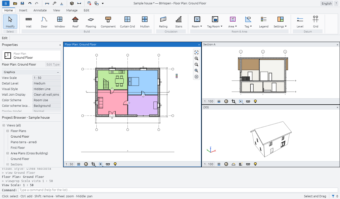
The Visual Style button of the view control bar, at the bottom of every view window, offers:
| Style | What is drawn |
|---|---|
| Wireframe | Every edge, also those behind other faces; no faces |
| Hidden Line | Faces in the paper colour and the edges in front of them |
| Shaded | Faces lit, in the colour of their material |
| Shaded with Edges | As Shaded, with the edges in front |
| Consistent Colors | Faces in the colour of their material, the same whatever the light |
The style belongs to the view and can be undone. The keyboard shortcuts WF, HL and SD
choose Wireframe, Hidden Line and Shaded.
The edges are the real ones: where two faces meet at an angle, and the outline of each face and each opening. A wall with a window shows its own outline and the window's, and no line where the pieces of the wall meet.
Plans, sections and elevations have a visual style too. A plan is drawn in Hidden Line until another style is chosen; in Shaded its floors, seen from above, take the colour of their material, and the faces of sections and elevations take their materials' colours.
Sun and shadows
In a 3D view the view control bar has two more buttons:
- Shadows On / Shadows Off: in the shaded styles the sun lights the model and casts shadows, from the walls onto the floors, from the roof's eaves onto the walls;
- the sun path button: Sun Path On draws a compass ring on the ground around the model, with the four points of the compass, the sun's path through the day as an arc over it, and the sun where it is. Sun Settings… sets where the sun is:
| Mode | What it takes |
|---|---|
| Still | Latitude, Longitude, Time zone (UTC), the day and month and the Time: the sun's position follows |
| Lighting | Azimuth (degrees clockwise from north) and Altitude |
Each view has its own sun settings, and the changes can be undone. Shadows are drawn by the 3D window on the graphics card; plans, sections, elevations and exported images do not show them yet.
Plans and their view range
View ▸ Create ▸ Plan Views ▸ Floor Plan opens New Plan: pick the levels and the scale, then OK. With Do not duplicate existing views on, the levels that already have a plan are left out; turn it off to make a second plan of a level.
A plan is a horizontal cut of the model at the Cut Plane of its view range. Walls crossing the cut plane are drawn cut, with the cut patterns of their layers' materials at Medium and Fine detail; lower walls and the floors of the level are seen from above.
To change the view range, select nothing (so that Properties shows the view), then View range ▸ Edit…. Each plane is measured from a level, with an offset:
| Plane | Level |
|---|---|
| Top | The plan's own level (Associated Level), the Level Above, a level by name, or Unlimited |
| Cut Plane | Always the plan's own level |
| Bottom | The plan's own level, the Level Below or a level by name |
| View Depth | As Bottom, or Unlimited |
OK sets the four planes together, as one change. They must stay in order, from the top down (top, cut plane, bottom, view depth): otherwise the window explains what is wrong and stays open. Floors below the bottom, down to the view depth, are drawn beyond in thin lines; so are floors a little under the bottom, such as a sunken slab, even with the view depth at the bottom.
Light and dark background
Options ▸ Theme ▸ Dark (or Invert background color) turns the drawing area dark. As on an inverted background, black lines, text and patterns are drawn light, colours keep their hue, and colour fills such as the rooms' are darkened, so the text over them stays readable. Options ▸ Interface size makes the whole interface bigger, from 100 % to 250 %, on top of the screen's own scale: useful on screens with many pixels. It is kept for the next start.
Opening a view from its symbol
Double-click a view's symbol to open its view: a section line or its head, an elevation symbol, a callout's boundary (a reference callout opens the view it points at), a level's line in a section or elevation (its floor plan opens), or a view placed on a sheet. The view's window becomes the active one.
View ▸ Create ▸ Elevation ▾ ▸ Framing Elevation makes an elevation of a grid: click beside the grid, on the side to look from (before the click, a line and an arrow show the view). The elevation looks at the nearest grid, as wide as the bay between the grids that cross it and as deep as the next grid parallel to it.
Scale, detail level and crop region
The view control bar shows the view's View Scale and Detail Level (in 3D views too).
- At a smaller scale the model is drawn smaller on paper while text, tags and symbols keep their size on paper: at 1:200 a text covers twice as much of the model as at 1:100.
- At Coarse a cut wall is one fill; at Medium and Fine its layers show, each with its material.
Sections cut the model the same way. Walls, floors and roofs that meet in the cut are drawn as one: a thick outline round them, a thin line only where two materials meet, none between two parts of the same material; walls attached to a roof stop under it. Each cut layer has its material's cut pattern (at Coarse, the type's Coarse Scale Fill Pattern in its Coarse Scale Fill Color, set on wall, floor and roof types, else one solid fill). Furniture and plumbing fixtures are never cut: they are seen whole. A window is cut with its frame in the thick cut line and its glass in thin lines; what lies beyond the cut is drawn in thinner projection lines.
Crop View clips the view to its crop region, Show Crop Region draws the region; drag its edges to resize it. To type its size: Properties ▸ Size Crop ▸ Edit…, then Width and Height; the region keeps its centre.
Hiding and isolating
Temporary Hide/Isolate (the glasses on the view control bar) acts on the selected elements, in the active view only, and does not change the project:
| Command | Shortcut | What stays visible |
|---|---|---|
| Isolate Element | HI |
Only the selected elements |
| Hide Element | HH |
Everything but the selected elements |
| Isolate Category | IC |
Only the categories of the selected elements |
| Hide Category | HC |
Everything but those categories |
The view gets a coloured border. Each use narrows what is shown: hiding one element and then
another hides both. Reset Temporary Hide/Isolate (HR) shows everything again; Apply
Hide/Isolate to View hides for good what was hidden for now.
To hide for good in the view, select the elements, then right-click ▸ Hide in view ▸
Elements or Category, or the contextual tab's View ▸ Hide in View, or type EH
(elements) or VH (category).
Reveal Hidden Elements (the light bulb on the view control bar, or RH) frames the view in
magenta and shows what is hidden in magenta, the rest in halftone. A hidden element can then be
selected and shown again: right-click ▸ Unhide in View ▸ Elements (or Category). Click
the light bulb again, or type RH, to leave.
Visibility/Graphics
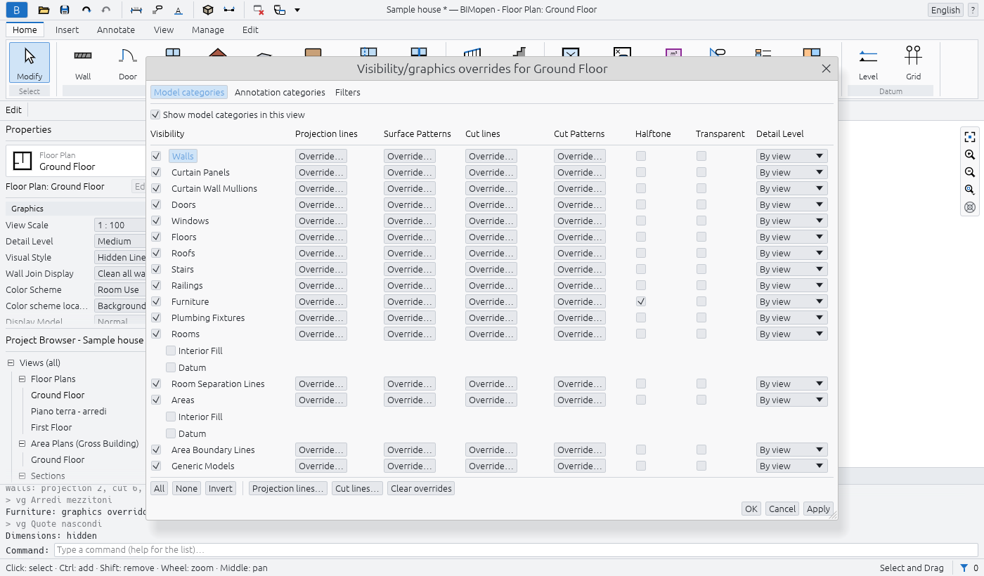
View ▸ Graphics ▸ Visibility/Graphics (or VG, or Properties ▸ Visibility/graphics
overrides ▸ Edit…) shows, for the active view, one row per category:
- the check box shows or hides the category; Show model categories in this view shows or hides them all;
- Projection lines and Cut lines: Override… sets the weight, colour and pattern;
- Surface Patterns and Cut Patterns: the material's patterns, hidden, in another colour or replaced by another fill pattern;
- Halftone blends the lines with the background;
- Transparent makes the surfaces see-through in the 3D view;
- Detail Level draws the category at another level than the view.
Clear overrides takes the selected rows back to the object styles. Changes show at once: Apply keeps them and the window, Cancel (or the window's ×) takes back what was not applied, OK keeps them and closes.
One element can have its own graphics in a view: select it, then right-click ▸ Override graphics in view ▸ By Element… (or the contextual tab's View panel). View-Specific Element Graphics has Visible, Halftone, Transparent, the surface and cut patterns and the projection and cut lines. They apply only in this view, over the category's and the filters'.
Filters
View ▸ Graphics ▸ Filters lists the project's filters: New, Duplicate, Rename, Delete. A filter has categories and up to four rules on their parameters, all of which an element must meet.
In Visibility/Graphics ▸ Filters, Add applies a filter to the view; its row then sets visibility, lines, Halftone and Transparent for the elements that pass it. Where filters disagree, the one higher in the list wins: Up and Down move the selected filter.
View templates
View ▸ Graphics ▸ View templates ▸ Create template from current view keeps the view's scale, detail level, visual style, view range and graphics as a template, by name. View templates ▸ Apply template to current view gives them to another view of the same kind: a plan (a second plan of a level too), a section or elevation, or a 3D view. A view does not follow later changes of its template until it is applied again, and the graphics of single elements are never part of a template.
Managing views
Right-click a view in the Project Browser:
- Duplicate View ▸ Duplicate copies the view with its properties; Duplicate with Detailing copies its dimensions, text, tags and 2D details too. The copy opens;
- Rename… asks for the new name (Rename View); names stay unique among views.
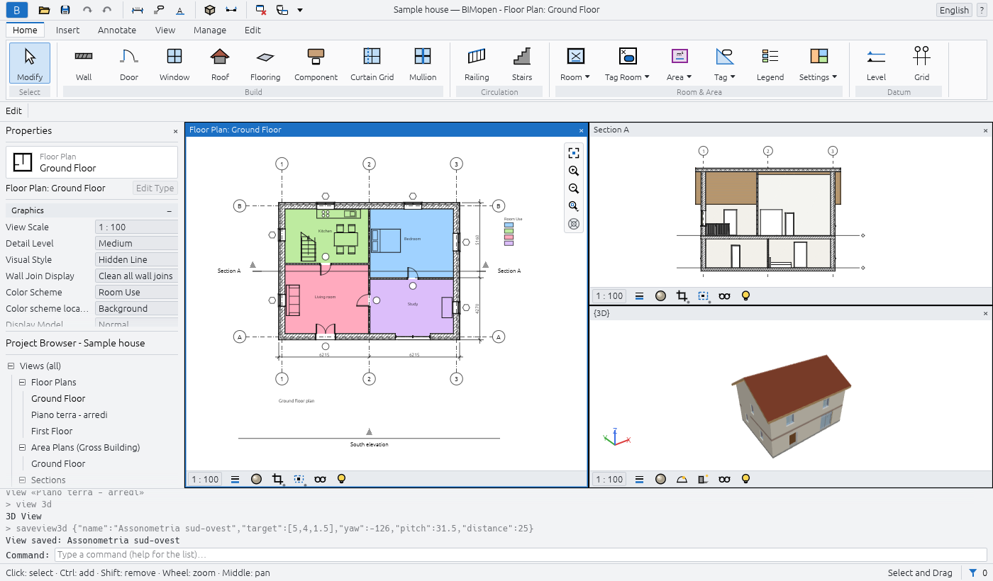
View ▸ Windows ▸ Tile shows all the open views side by side, filling the drawing area: with three windows, the active one on the left at full height and two stacked on the right.